Plots for Unequal Binary mark 1 v8 run with resolution of 258 x 258 x 256, mmax = 30, and (20,5) ADI iterations
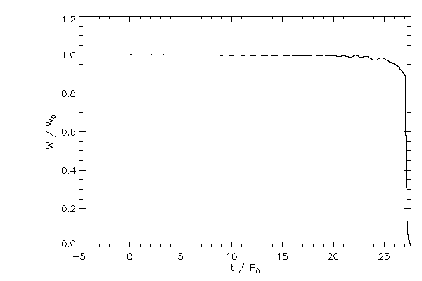
Separation |
 |
 |
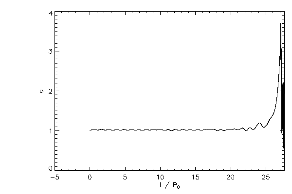
| The three-dimensional binary separation (left) and normalized to its initial value (right) |
Masses |
 |
| The mass ratio = M1 / M2 where star 1 is the one along the positive x axis initially |
 |
 |
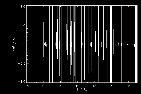 |
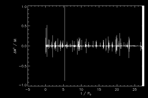
| Time derivative of the mass of each star, normalized to the orbital period divided by the total mass |
 |
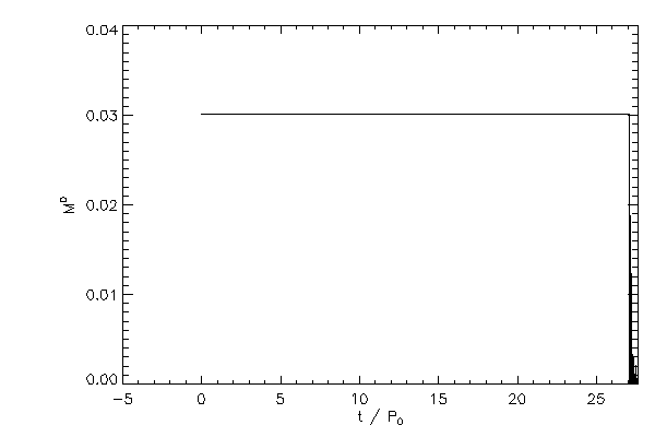 |
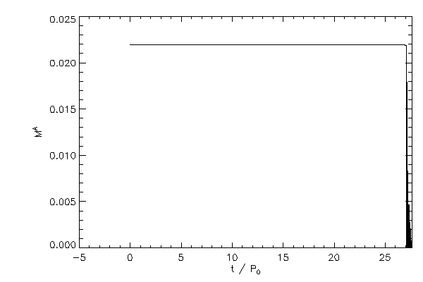
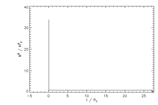
| The mass of star 2 (left panel) and star 1 (right panel) where the mass is determined by the average
energy of the boundary layer of each star |
 |
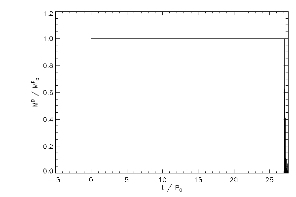 |
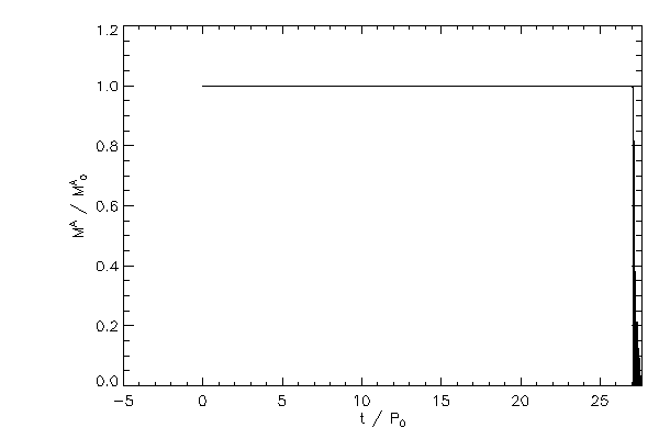
| The mass of each star, normalized to their initial values |
 |
 |
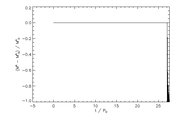
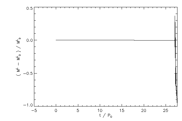
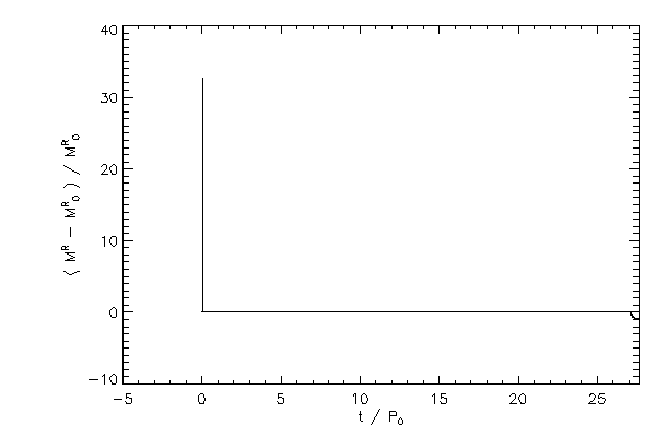
| The relative change in mass of each star |
 |
 |
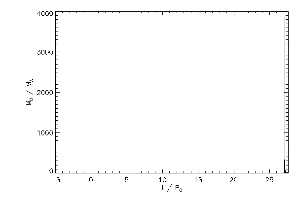
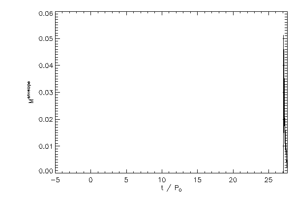
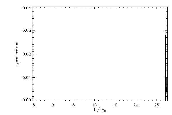
| The mass in the envelope (not bound to either star) in the left panel and the
mass advected off the active grid (right panel) |
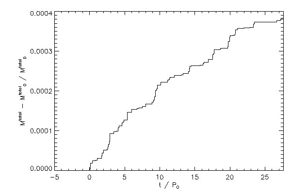 |
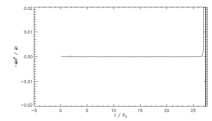
| The relative change in the total mass - including boundary zones |
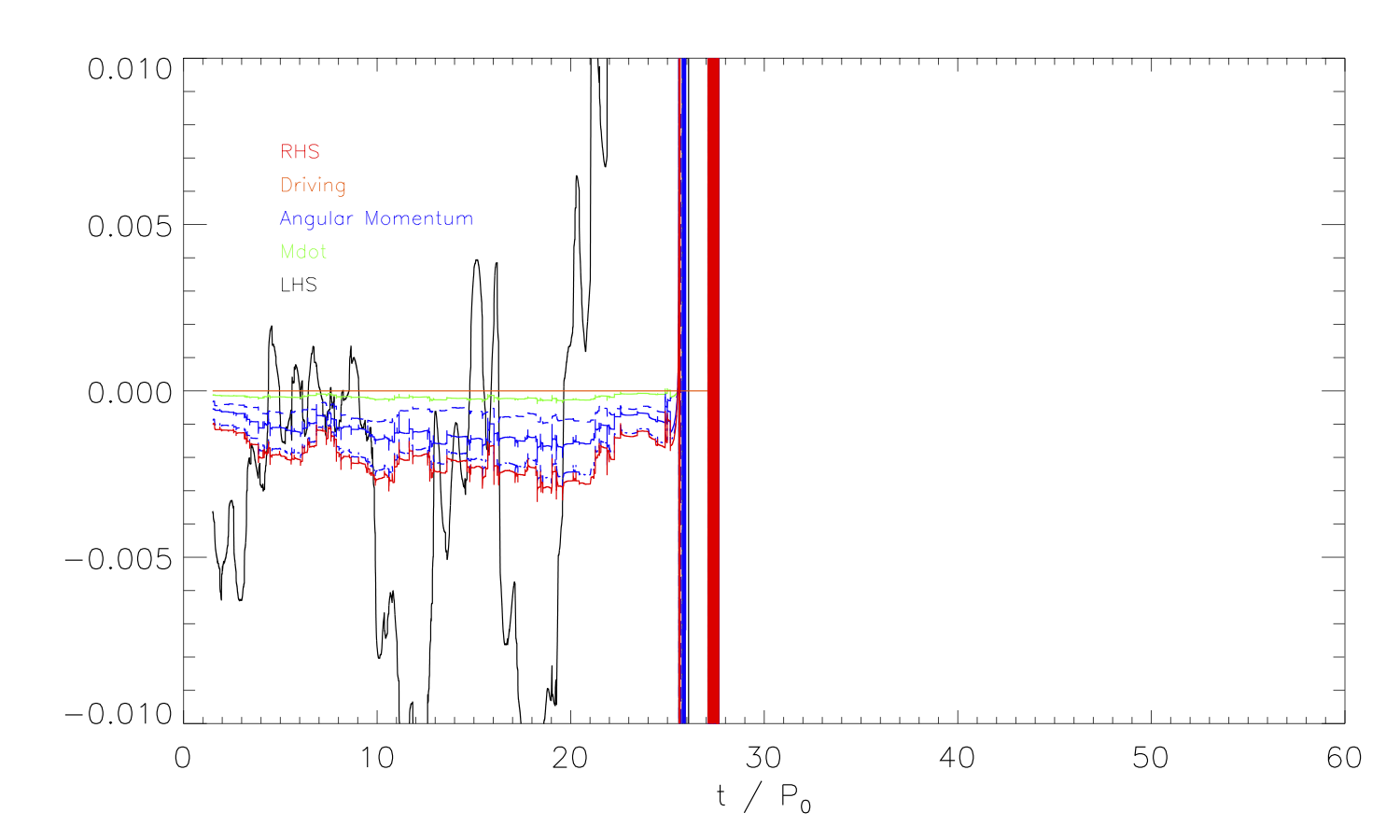
Angular Momentum |
 |
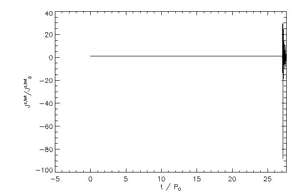 |
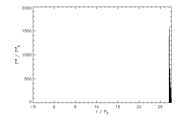
| The total z component of angular momentum in code units (left panel) and normalized to its inital value
(right panel) |
 |
| The relative change in the total z component of angular momentum |
 |
 |
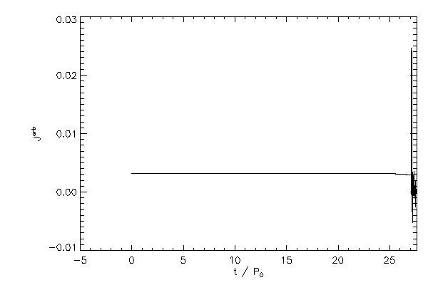
| The orbital angular momentum of the binary (left panel) in code units and normalizes to
the initial, total z component of angular momentum (right panel) |
 |
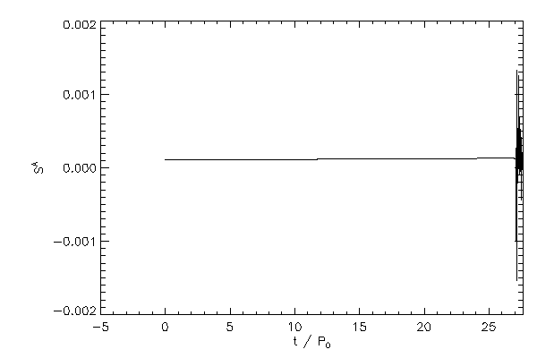 |
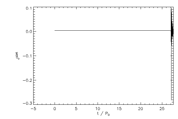
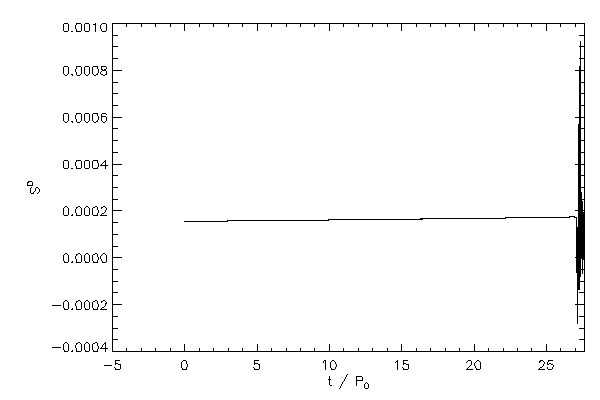
| The z compnent of spin angular momentum of star 1 (left panel) and star 2 (right panel) |
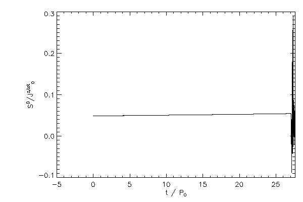 |
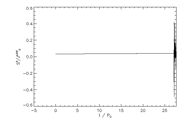 |
| The z component of spin angular momentum for each star normalized to the initial, total z
component of angular momentum |
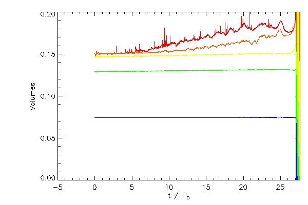
Volumes |
 |
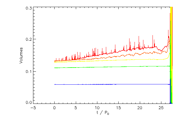 |
| The Roche volumes for star 1 (left panel) and star 2 (right panel) as white curves and for each
star the volume occupied by material more dense than 10-5 (red), 10-4 (orange),
10-3 (yellow), 10-2 (green), 10-1 (blue).
|
Center of Mass |
 |
 |
| Center of mass of each star and system in code frame (left) and inertial space (right) |
 |
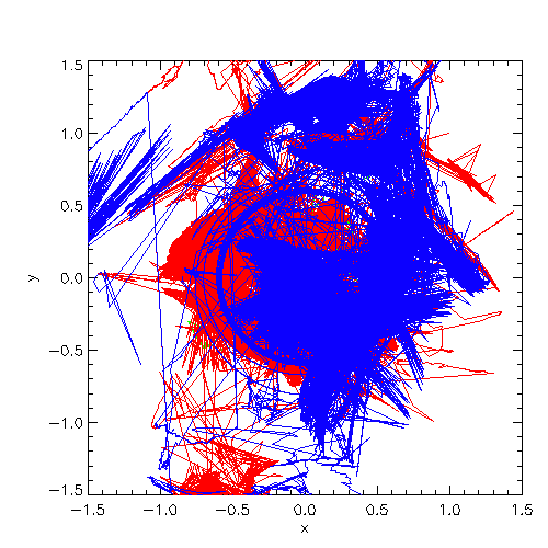 |
| Trajectories of the system center of mass (green), star 1 (red), star 2 (blue) in the code reference
frame (left) and in inertial space (right) |
 |
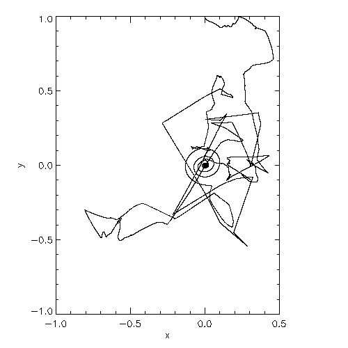 |
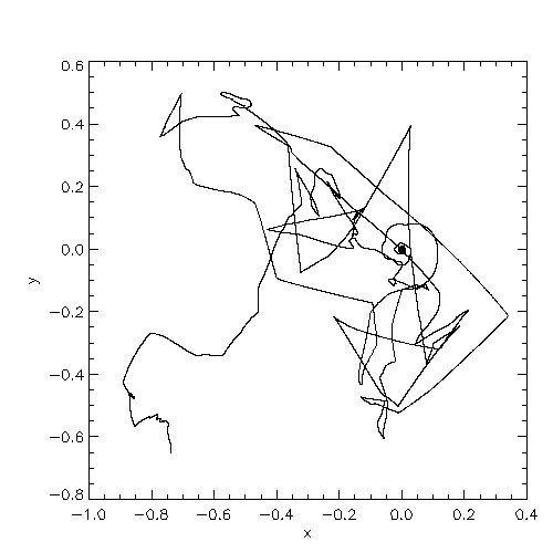
| Blowups of the system center of mass location in the code reference frame (left) and in inertial space (right) |
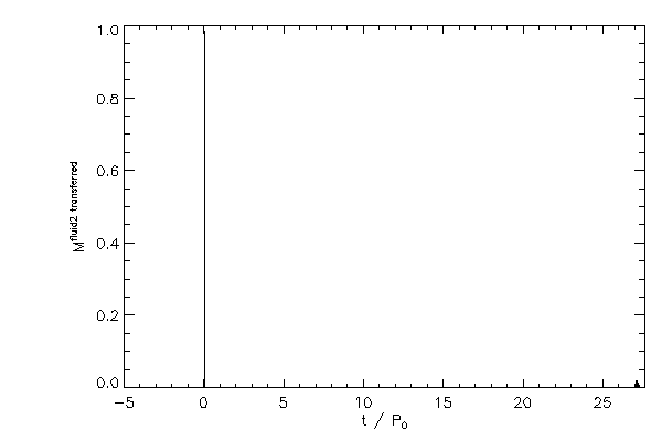
Masses from Gas Fractions |
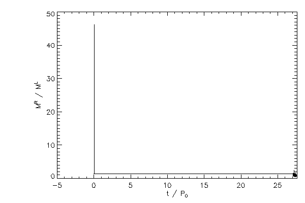 |
| The mass of the right hand star (from both fluid components) divided by the mass of the
right hand star as a function of orbital time |
 |
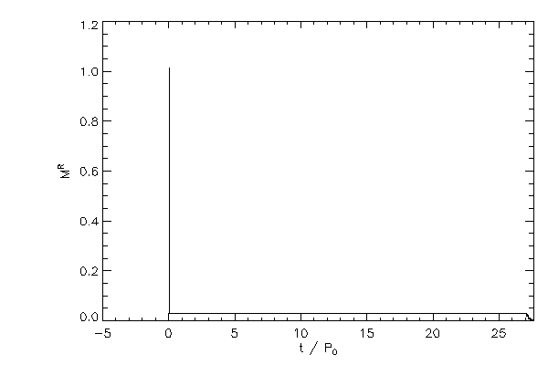 |
| The mass of the right hand star (right panel) and the left hand star (left panel) |
 |
 |
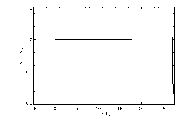
| The mass of each star, normzlized to their respective initial values |
 |
 |
| The relative change in the mass of each star |
 |
 |
| The mass of fluid type 1 in the left hand star (left panel) and the mass of fluid 2 in
the right hand star (right panel) |
 |
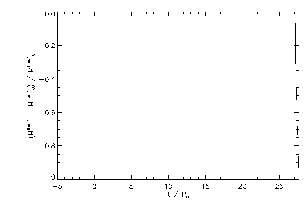 |
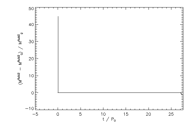
| The relative change in mass of fluid type 2 (left panel) across the grid and the same
quantity for fluid type 1 (right panel) |
Density |
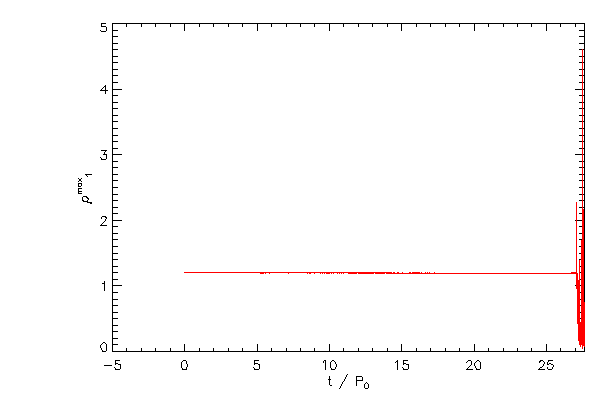 |
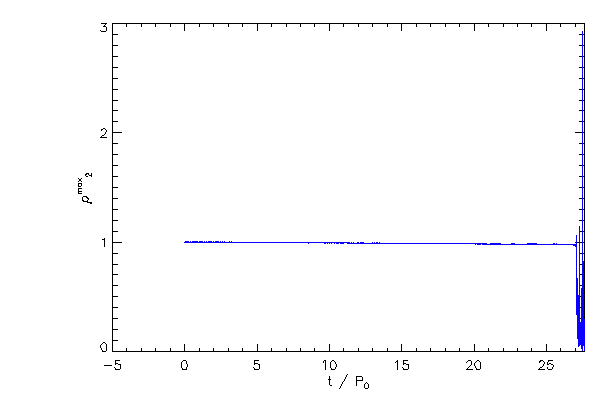 |
| The maximum density of the right hand star (red) and left hand star (blue) |
 |
| The location of the density maxima in the code reference frame |
 |
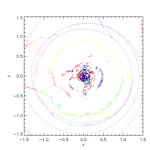
| The location of the density max in the equatorial plane |
Roche Potential |
 |
 |
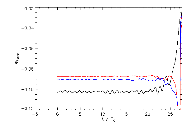
| The left panel shows the value of the Roche potential at L1 and the right panel shows
the location of the L1 point (white), and the outer edges of the Roche lobe for star 1
(red) and star 2 (blue) in the code reference frame |
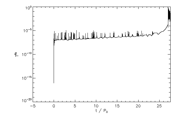
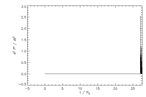
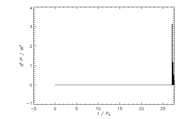
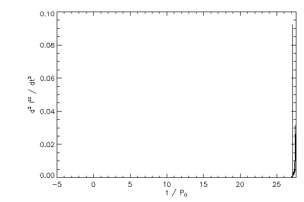
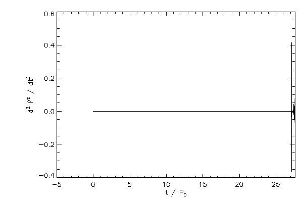
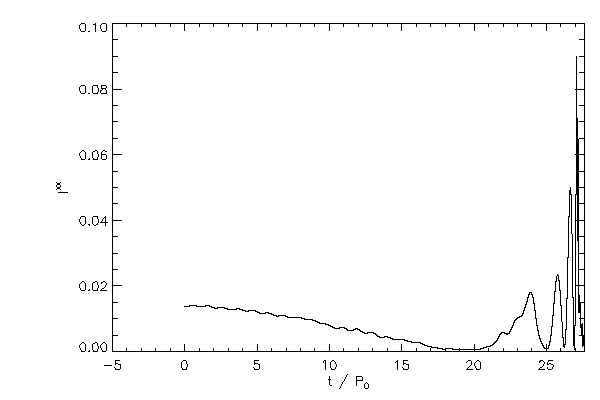
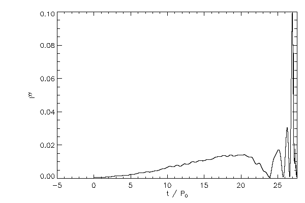
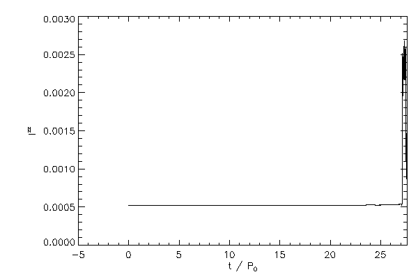
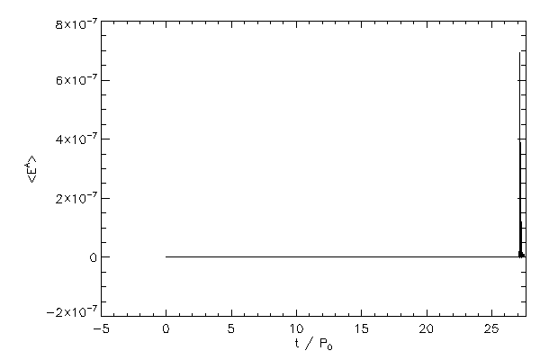
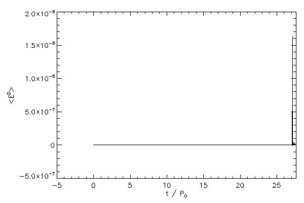
Second time derivatives of the moment of inertia tensor, Iij |
 |
 |
 |
 |
 |
 |
Moments of Inertia |
 |
 |
 |
| Principal moments of inertia calculated in the code frame coordinates |
Boundary Energy |
 |
 |
| The average energy of cells in the boundary layer of star 1 (left panel) and star 2 (right panel) |
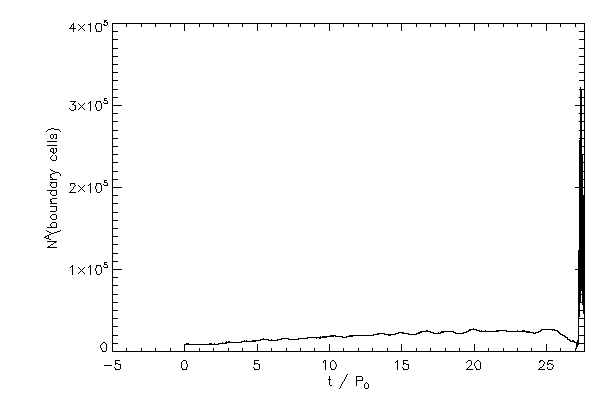 |
 |
| The total number of cells in the boundary layer of star 1 (left panel) and star 2 (right panel) |
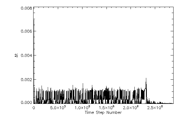 |
| Simulation timestep increment |
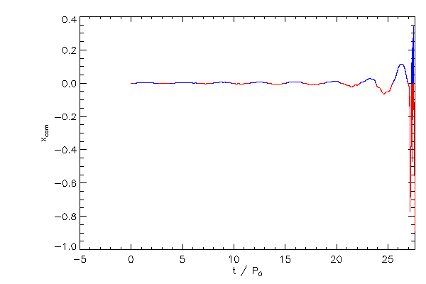
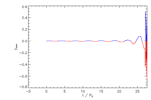
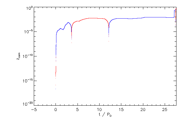
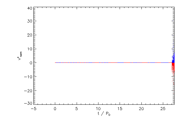
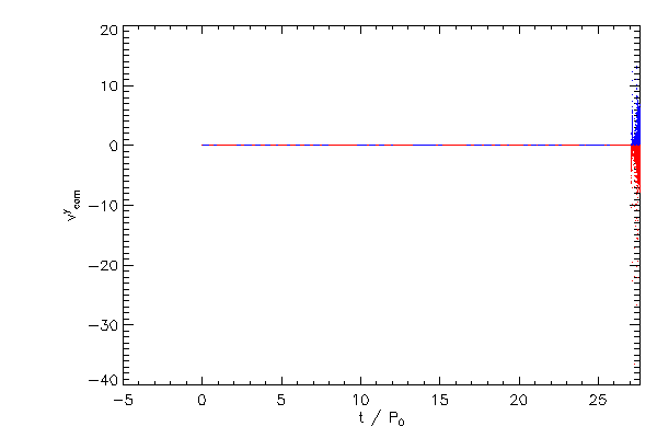
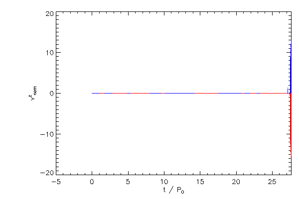
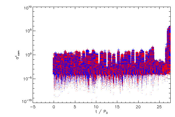
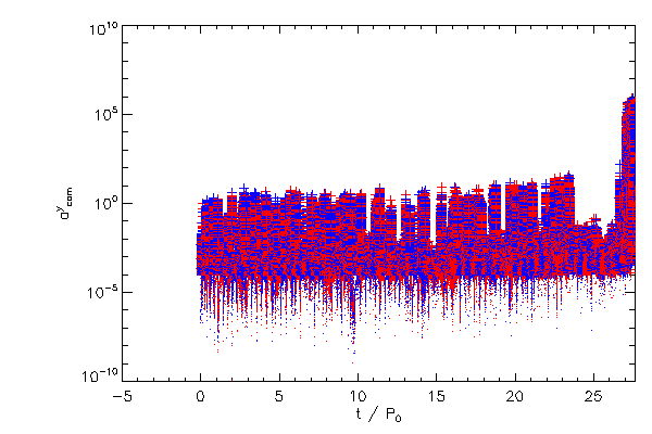
Center of Mass Correction |
 |
 |
 |
 |
 |
 |
 |
 |
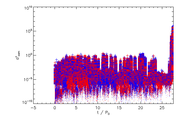 |
| The Cartessian components of the center of mass correction terms, in the code reference frame |